Revisiting the R&WI Pilot Report: The Hughes Hotrod
We Take a look at an excerpt of one of R&WI’s earliest pilot reports from the March 1969 issue — chosen based on a readers’ poll.
The term “hotrod,” derived from teenage efforts of a decade ago to soup up stock automobile engines, technically has little in common with Hughes’ entry in the small executive helicopter field. The capability of that aircraft, however, has a lot in common with the now fundamental American slang expression.
Performance of the aircraft has been evident in various reports over a considerable amount of time. It began with Hughes’ capture of the LOH-6 military contract to provide a turbine replacement for aging H-13 and H-23 piston-driven light observation helicopters.
In the process of developing the military hardware, the OH-6A, production version of the LOH-6, walked off with an impressive variety of “firsts” in the rotorcraft field. These, as indicated in the company’s handouts, include 23 world records in three separate categories of helicopters. These include speed, distance and sustained altitude marks.
Hughes production was devoted to meeting military contracts until this year, with minor exceptions. These included, we have been told, a small number of “civilianized” OH-6As, prepared for the exclusive use of the leader of a foreign country, and at least one Hughes demonstrated to keep the industry mindful of the company’s ultimate intent to go into the civilian market.
The Whirly-Girls, our worldwide group of female rotorcraft flyers, chided the Hughes people (longtime supporters of their organization) for having the helicopter with the most repainted exterior in existence. Toni Page pointed out that the one 500 demonstrator had received a different color scheme at least bi-weekly over a period of many months, while its sister aircraft were given mundane, olive-drab exteriors.
The two aircraft with which the Hughes task force arrived at the HAA Convention in Ft. Lauderdale, Florida, January 1968 were only a slightly different story. They had an improved interior finish to provide the executive environment and an enlarged rear compartment window, providing vision below the seat level. They also were both white, with a simplified trim design.
The ultimate civilian configuration, expected in May 1969, would further improve the doors, particularly in overall size and in hinging arrangement, and relocate the blower, which now protrudes between the two rear passenger seats at ear level.
The 500 is currently the only aircraft employing he Allison 250-C18A. The “A” differs from the 250-C18, used by the aircraft’s two competitors, only in the location of the combustion chamber fuel drain line. Due to the 44-deg powerplant inclination in the Hughes, the rearward low-point drain plugged in the C18, is connected to the overboard plumbing.
There are several advantages to the Hughes approach to small executive transport, the most notable resulting from the OH-6A engineering in the area of maintenance. The company advertises a product requiring only 300-hour inspections and a 1,200-hour overhaul.
The rotorhead, which contributes largely to this claim, is exceedingly unique in design concept. Each of the four blades is attached at the point of a metal “wishbone” by a vertical retaining bot. The “wishbone” is connected to the corresponding unit serving the opposite blade. The blade swings forward and rearward while articulating around its individual retaining bolt, while the centrifugal force is balanced out by the corresponding force on the opposite blade.
Flapping and pitch change action are accomplished by flexing the “wishbone,” a strap pack of 15 high-strength stainless steel straps.
In the original design the “wishbones” were covered by an aerodynamic cuff. This has been removed in civilianizing the craft when its usefulness proved questionable.
Hughes representatives said that no maintenance is required on the head between overhauls. Since there is little metal-to-metal movement involved, service is largely limited to a disc-type damper installation serving each blade. It appears similar to the damper system employed on Hughes 269A/B articulating rotorheads.
The transmission is hardly more complex than the differential of a large truck. There once were rumors in the industry that the similarity was more than mere happenstance. Regardless, the transmission, actually a redesign of the 269 series gearbox, represents an ultra-simple installation in the comparative sense.
The input shaft from the turbine gearbox enters at the lower rear section of the transmission. A simple bevel spur gear at the input shaft drives a bevel plate gear mounted on the rotor output shaft. This, in turn, drives the tail rotor shaft to the rear, and through a second bevel spur gear, the main rotor drive gear at the forward end. Total reduction of the 6,000 rpm input is handled by the two bevel gear meshes.
Hughes said it had never heard of a transmission failure since the LOH-6 was first flown.
The transmission does not support the weight for the aircraft, and hence can be removed as a unit without disturbing the main rotor system or its controls by simply removing four bolts. This feature is made possible by the dynamic forces of the balanced blade system being absorbed by a static mast/thrust bearing installation. The transmission is splined into the lower end of the mast. Removal is accomplished through the rear wall of the rear compartment.
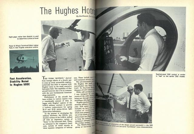
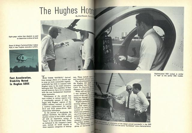
To further simplify maintenance, there are only three sight gauges and no grease fittings.
The turbine is exposed for easy access by two clamshell doors, which constitute the lower rear end of the fuselage pod. The original exhaust system, which consisted of a common manifold with one outlet, has been modified to a dual installation, which can be identified at the outboard end by a centerline separation.
What appears to be a stiff-legged gear arrangement is actually a telescoping fairing around a shock-mounted strut. At the rear these oleos enter the fuselage near the forward end of the engine compartment. There the strut makes an abrupt obtuse angle to its pivoting anchor point near the fuselage centerline.
At the top of the bend, a shock strut is connected between the skid support and an anchor point above on the inside of the fuselage.
Externally, only the telescoping fairing is noticeable when the gear is required to flex. Again, it appears very similar to the concept of the skid-support arrangement on the 269 series, an exceptionally well-engineered installation, which rated praise, even from its competitors.
Carrying through, the anti-torque rotor and related drive system are largely copies of 269 series units. The tail rotor noise, reminiscent of a bumblebee, is deceivingly reduced, however, from the similar-sounding 269s. We are told the noise comes from the design, rather than the speed. The 500 turns at a lowly 3,200 rpm.
Design simplicity, again, was the key in design of tail rotor drive shafting. The anti-torque drive has no hangar bearings.
Hughes also has allegedly experienced none of the ice and snow problems of its competitors. One company pilot told us that he had flown the ship through Canada and Alaska in a variety of heavy snow conditions, in temperatures down to minus 20 deg F, and experienced no difficulty.
Why the snow, or refreezing ice, does not affect the 500 may be attributed to the fact that the turbine is buried deep in the fuselage and that the intake air is pulled in from above, through the rotating mast and controls.
Cabin heat is drawn directly from the bleed ports between the fifth and sixth stages of the Allison compressor. Getting it to the cabin is a simple matter of ducting. Pilots who flew in Alaskan snow tests state that the output is sufficient to provide far more heat than the passengers require at minimum temperatures.
The bleed of fifth-stage air is acceptable due to the minimized power requirements, and its loss has no effect on operational performance.
Operationally, the aircraft does perform like a hotrod.
The ship flown by R&WI still maintained the 243 max continuous horsepower limitation, although there is a military-sponsored program to increase this figure to a more reality employment of the 250-C18A’s maximum capability.
We found, upon entering the cockpit, that it, to the point of redundancy, appeared and felt much like a sophisticated version of the Hughes 300. The feeling extended to the slop of the windshield and psychological response to instrumentation.
Fuel control actuation is accomplished on starting at the standard 15%, common to all 250-C18 series turbines, by simply twisting the throttle to the idle position. The shutoff stop is controlled by a collar-type disc at the forward end of the throttle. To bring the control to the shutoff position requires sliding the hand forward and lifting the disc away from the rotating portion of the twist grip. From that point on, there was nothing unfamiliar in lighting the fire.
Due to reduction of the powerplant output, a mere matter of relocating the limits on the engine instruments, the engine is literally operating at all times within its design cruise range. As a result, there is no way the TOT could exceed its limits as long as the torque gauge is properly monitored. In a short time, it was back to flying to torque gauge as if I were reading manifold pressure.
My experience in the 500 included about 1.5 hours of enjoyably kicking it around.
I was annoyed by the lack of a rate-of-climb instrument and a sticking ball in the turn and slip indicator. The latter was just assumed to be a slightly out-of-rig condition, until full rudder deflection in both directions at 40 mph failed to cause the ball to move. Subsequent examination verified the ball to be frozen at one half a ball width to the right.
Discussion with Hughes has pointed out that the anti-torque system, augmented in flight with a considerable area of “tail feathers,” is designed to give a capability of unlading the tail rotor at an optimum speed of 50 mph. The range of tail-rotorless operation conceivably extends from 30 to about 70. As a result, as the speed increases, the purely mechanical control system demands considerable extension of the right pedal. In proper rig, the pedals should pass a common point at 115.
Acceleration is fast. The ship, with all that power to spare, had no problem holding a cruise of 140 mph for me. The spec sheet calls for 144 as standard, and the redline of 150 is easily attainable, though vibration level begins to rise.
One quality of considerable note is the aircraft’s stability. Jamieson had, in demonstration, literally slapped the stick all over the cockpit.
During my own flight, it seemed normal to let go momentarily and find the stick in the same place when you reached for it again.
The eight autorotations I personally executed were smooth. They spanned overheads, straight-ins, 180s and combinations to a pot. Some were at 85 mph, others below 40. First impressions, again, were that the sink rate was quite close to that of the 300. With no rate-of-climb it was difficult to be precise.
The book calls for a standard, at 60 kt, of 1,380 fpm, maintaining 485 rotor rpm. The 300 textbook autorotation is close at 1,450.
The flexibility of the 500 in an autorotation, however, is extensive. The factory claims a 6-to-1 glide ratio at the higher speed of 85 kts.
My final was shot from 2,500 feet. At 35 mph the point of impact was just ahead of my rudder pedals. Increasing the speed to 60 and stabilizing moved the impact point up to midway of the Ft. Lauderdale runway. By dropping the nose and picking up 85 mph, the point of touchdown moved to the far end of the runway, even after the previous loss of altitude. RWI