Breaking Down the Bell 525 Crash Report
With vibration found to be the cause of the Relentless prototype’s 2016 crash, Bell applies lessons learned to fly-by-wire technology.
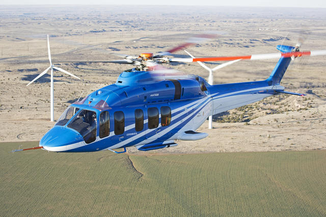
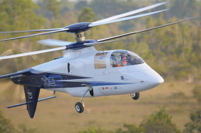
In 2012 under a flurry of lights at Heli-Expo in Dallas, Bell Helicopter (as it was called at the time) unveiled the 525 Relentless. Dubbed a “super-medium-lift” twin-engine utility helicopter, the Relentless was to be the first commercial helicopter with a fly-by-wire flight control system. Bell set its sights on the offshore gas and oil industry as its ideal target customer.
The 525 took its first flight July 1, 2015. Then just a year later, on July 6, 2016, tragedy struck. During a developmental test flight in Texas, the Bell 525 prototype crashed, fatally injuring the two test pilots on board. The chase aircraft reported a main rotor blade was seen to be flying “out of plane.” Seconds later, the main rotor contacted the tailboom, with disastrous results.
Jan. 16, 2018, nearly two years later, the National Transportation Safety Board (NTSB) released its full report on the crash, citing severe vibration as the probable root cause of the loss of the aircraft and crew.
The report’s findings are so meticulously laid out that it’s easy to forget the entire catastrophic event unfolded within approximately 21 seconds of initiating the test point. Despite being extremely experienced and disciplined, Bell test pilots Erik Boyce and Jason Grogan had little time to sort out the complex physical phenomena they were experiencing.
The Test
As described in a narrative provided by Bell after the NTSB’s report was released, the 525 prototype was demonstrating the ability to recover from a single-engine failure at high airspeed, high power setting, heavy gross weight and forward center of gravity (CG).
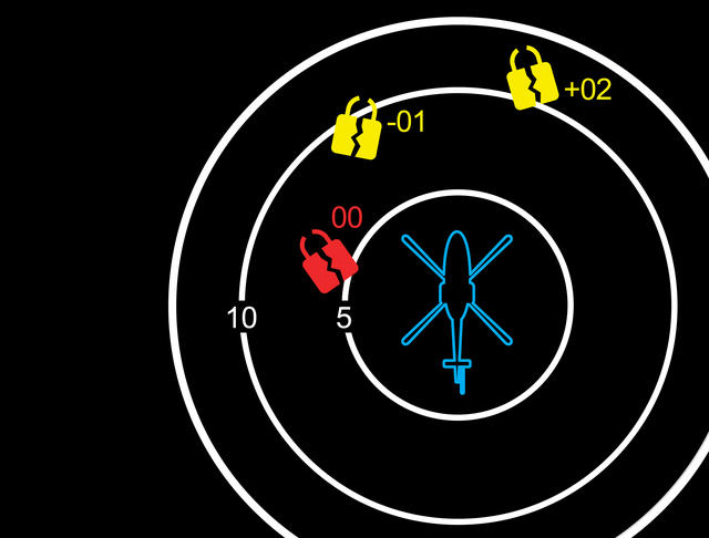
The simulated engine failure was to be the last in a series performed at increasing airspeeds that day and was initiated at the aircraft’s never-exceed velocity (Vne) of 185 kt. From a nominal 100%, the rotor RPM decayed as expected, and the pilot waited the prescribed one second before reducing collective to begin recovery. Recovery stopped the main rotor RPM decay at approximately 92%, but did not restore it. At this high airspeed and low RPM condition, an unanticipated vibration developed.

The Bell summary went on to say that the vibration propagated into the cockpit, where it was amplified in a “biomechanical feedback loop,” as descibed by the NTSB, involving involuntary oscillations of the collective lever. The aircraft’s stabilization system also contributed to the feedback loop. The vibration grew rapidly, and approximately 12 seconds after initiating a recovery attempt, the RPM fell below 80%, the main rotor blades strayed out of the normal plane of rotation and the tailboom was severed, followed by an in-flight breakup of the aircraft.
The Science
It is intuitively clear that helicopters are prone to vibration. But what may be less apparent is that, as required by certification, great lengths are taken by engineers to “design out” any resonant frequencies that might occur between components.
Resonance is the tendency of a system to vibrate with increasing amplitude when it’s exposed to an external force whose frequency of vibration is closely matched to the system’s natural frequency. That is an elaborate way to describe exactly what we all learned as children at the playground: pump your legs at the right time on the swing set to match the swing’s natural back-and-forth frequency, and you add energy, which makes the swing go successively higher.
But the science of aircraft vibration analysis is more complex because an aircraft moves in six degrees of freedom, not just one. Despite the computer modeling and shake table testing performed during development, the initial testing did not uncover the situation that would put the helicopter into its catastrophic vibratory mode.
According to the NTSB report, the combination of steady high speed and low rotor RPM caused an excitation of a “scissors-mode” vibration. In this mode, adjacent main rotor blades began to lead and lag together and apart like the blades of scissors. This action created a fore and aft rocking motion of the mast occurring six times per second, or 6 Hz. This rocking, in turn, excited a vertical bending of the fuselage. With the nose and the tail of the aircraft now going up and down in a u-shaped fashion at 6 Hz, the pilots experienced that same frequency as a vertical motion in their seats.
Closing the Loop
Normally a pilot will command an aircraft to reach a desired condition by assessing its current state, making a control input, judging the aircraft’s response and then making another input to correct any perceived error in a continual “closed loop”. The rate and aggressiveness at which the pilot makes these inputs is referred to as “gain.”
As the Bell 525 has a fly-by-wire control system in lieu of mechanical flight control linkages, pilot inputs are fed into signal processors and interpreted by flight control computers. Control laws then determine how much to move the actuators at each control surface and at what level of gain.

A virtue of fly-by-wire technology is that control system engineers can design out any tendency for pilot inputs to become out of phase with the aircraft’s desired response, which could increase any undesired motion and cause a pilot-induced oscillation. Control laws can also be made to account for known system vibratory modes and filter out any pilot input frequencies that may excite them. These laws must be designed carefully, however, so they do not negatively impact aircraft handling qualities.
In the case of the accident flight, the prototype did not have any collective filtering in its control laws. As the pilot held the controls of the 525 constant, the collective lever moved up and down at the same 6 Hz that was recorded at his seat, in “biomechanical feedback,” or, “unintentional control input resulting from involuntary pilot limb motions caused by vehicle accelerations,” as defined by NTSB.
The changes in blade pitch due to unintended collective motion were fed back into the control loop, adding energy to the scissors-mode vibration, further amplifying the pilot seat vertical motion in a continually intensifying condition. In this state, it was determined that the pilots were subjected to as much as 3G of vertical acceleration, likely making it very difficult to read the shaking displays and realize the worsening low rotor.
The aircraft’s attitude and heading reference system (AHRS), which serves in part to improve handling qualities by dampening out uncommanded accelerations such as wind gusts, also sensed the 6 Hz vertical and lateral airframe bending as a swashplate “stirring” motion. The system responded with its own 6 Hz control input in an attempt to dampen it, but this was shown to result in further excitation of the scissors mode.
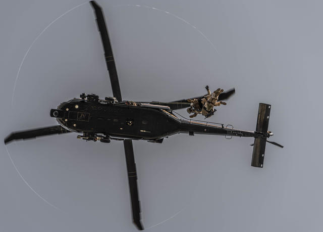
The “significant out of plane motions” described in the accident record are explained in Bell’s summary as “blade-to-blade thrust variations” due to a 6 Hz collective input to the main rotor, which was spinning at 4 Hz. Rather than producing a normal uniform thrust increase and simultaneous coning of the blades, the oscillatory collective inputs produced varying blade aerodynamic forces causing the independent out-of-plane motion and an atypical, blurred tip-path plane — as seen by the chase aircraft just prior to the crash.
Moving Forward
Flight testing of the 525 resumed July 2017, aiming for certification in 2019. The NTSB cited that although the test aircraft was fully instrumented for data gathering, the absence of a cockpit voice recorder and/or flight data recorder (which the aircraft was not required to have) made it difficult to assess what was occurring in the cockpit during recovery procedures. Bell acknowledges the production model 525 will have these systems, and all future Bell telemetered test flights will record audio.
Testing showed that the rotor modes of vibration were well damped at 100% RPM throughout the flight envelope. But on the accident flight, the normal transient rotor deceleration/acceleration after the power loss didn’t happen, and the steady state rotor RPM of 92% while at high forward speed is a key aspect of the event.
Changes to the 525’s control laws were added to incorporate a collective control filter to target vibration near the 6 Hz band. The pre-existing cyclic control filters were also tuned and deepened, as were the rate filters in the AHRS system.

Vertical shake table tests have since been performed with side-stick collective to determine and incorporate the pilot’s transfer function.
Bell plans to perform future one engine-inoperative (OEI) tests at 95 to 100% rotor RPM, incorporate a distinctive low-rotor tone and incorporate an automatic termination of one engine-inoperative mode should RPM drop below a certain limit.
The developmental phase of flight testing involves expanding the “flight envelope” of an aircraft through an incremental buildup of maneuvers, so that the limits of normal operation can be safely established. But the complexity of these machines cannot be overstated; and sometimes, even when using an incremental buildup to slowly chip away at test points, the edge of the envelope can be found inadvertently.
In the wake of such a tragedy, it is most certainly challenging to press on. But as professionals with a common passion for advancing and perfecting excellence within our industry, we owe it to test pilots Boyce and Grogan, who made the ultimate sacrifice, to learn what went wrong, make corrections, overcome the anguish and see the project to completion.
The Tacoma Narrows Bridge: A Lasting Lesson in Vibration
July 1, 1940, the Tacoma Narrows Bridge opened to traffic in the U.S. state of Washington. It was the third longest suspension bridge in the world at the time. Since its build, it had a distinctive up-and-down bounce that earned it the nickname “Galloping Gertie.”
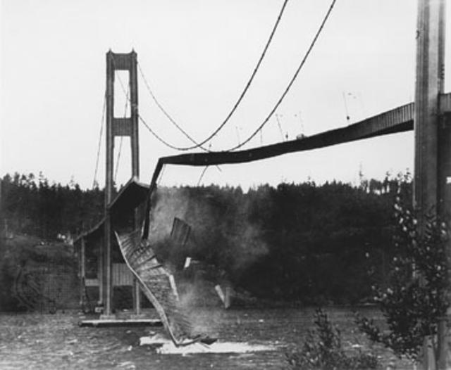
Engineers were anxious to correct the problem, and tried multiple fixes to quell its motion. None of these fixes worked, however, and Nov. 7 that same year, in 40 mph winds, a torsional vibration developed, which began increasing in amplitude. The increasing oscillation continued to deform the bridge until its spectacular collapse, which was caught on film.
For some time, this event was attributed to a classical case of the wind in resonance with the bridge’s natural frequency. But upon further inquiry and a better developed understanding of aerodynamics, the event is more appropriately explained as an aero-elastic phenomena, called “flutter.” In this case, aerodynamic forces added stored energy to the twisting motion of the bridge, which could not be dissipated by the bridge’s own damping. RWI